ESP-12F_Relay_X2
Product description
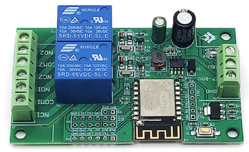
This is a 2-relay board with an ESP-12F. Each relay has COM+NO+NC exposed. Relay load of up to 250VAC or 30VDC. The board can be powered either via 7-80VDC, or via 5VDC (separate connectors). I bought it from: https://www.aliexpress.com/item/1005003516399175.html (no affiliation, no guarantee it will continue to exist). Search for more: https://www.aliexpress.com/wholesale?SearchText=esp-12f+relay+2+channel Technical specification here: http://www.chinalctech.com/cpzx/Programmer/Relay_Module/510.html (Link working 23 May 2024)
GPIO Pinout
This board has headers for every GPIO pin on its ESP-12F.
| Pin | Comment |
|---|---|
| 5V | Do not use 5V for programming |
| TX | 3.3V level! |
| RX | 3.3V level! |
| GPIO0 | 3.3V level! (pulled up, connect to GND for flashing) |
| GND | |
| GND | |
| Pin | Comment |
| —— | ————————————————- |
| 3V3 | For programming, inject 3.3V power here |
| 3V3 | For programming, inject 3.3V power here |
| 5V | |
| 5V | |
| GND | |
| GND | |
| GPIO5 | 3.3V level, Use a jumper to RY1 to enable Relay 1 |
| GPIO4 | 3.3V level, Use a jumper to RY2 to enable Relay 2 |
| GPIO0 | 3.3V level, Extra GPIO0 Header |
| GPIO2 | 3.3V level, Blue LED on ESP (inverted) |
| GPIO15 | 3.3V level |
| GND | |
| Pin | Comment |
| —— | —————————————- |
| ADC | 0V-1V only |
| EN | Pulled up |
| GPI16 | 3.3V level, Blue LED on Board (inverted) |
| GPI14 | 3.3V level |
| GPI12 | 3.3V level |
| GPI13 | 3.3V level |
Basic Config
esphome:
  name: esp12frelayx2
esp8266:
  board: esp12e
# Use the blue LED in the device as a status LED, which will blink if there are warnings (slow) or errors (fast)
status_led:
  pin:
    number: GPIO2
    inverted: True
# x2 relay outputs, exposed as switches in Home Assistant
switch:
  - platform: gpio
    pin: GPIO5
    name: Relay1
    id: relay1
  - platform: gpio
    pin: GPIO4
    name: Relay2
    id: relay2
  # Blue LED on Board (not ESP board) as switch in Home Assistant
  - platform: gpio
    name: Led16
    pin: GPIO16
    inverted: true