ESP32 Relay x1
Product description
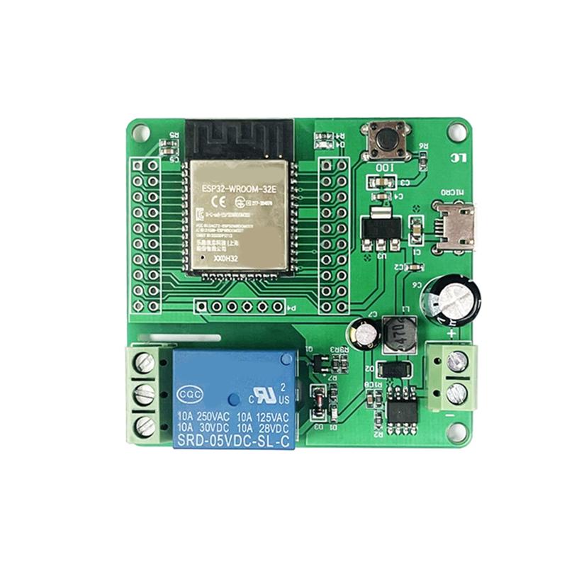
This is a 1-relay board with an ESP32-WROOM-32E. The relay has COM+NO+NC exposed and Each relay supports 10Amp max load (250V AC, 30A DC) The board can be powered either via 7-30VDC or via 5VDC via micro-USB (separate connectors). The onboard button is connected to GPI00, Status LED to GPIO23 and Relay to GPIO16 They are available from aliexpress.
GPIO Pinout
This board has headers for every GPIO pin on its ESP32 via 2 sets of 2x10 headers, and an additional 6 pin header below the ESP32 for flashing. The micro USB is for power only, no serial connection. I was able to flash it using the ESPhome web tool and an FTDI connector. I was able to use the 5V pin with the FTDI set to 5V as well and connected to the GPIO pins, but 3.3V should be used if possible (it would not flash for me at 3.3V). I was unable to flash with a USB cable.
| GPIO | Connected onboard to |
|---|---|
| GPIO0 | Button |
| GPIO16 | Relay |
| GPIO23 | LED |
Basic Config
esphome:
  name: ESP32 relayboard
esp32:
  board: esp32dev
  framework:
    type: esp-idf
# Enable logging
logger:
# Enable Home Assistant API
api:
  encryption:
    key: "xxxx"
ota:
  password: "xxxx"
wifi:
  ssid: "wifi_ssid"
  password: "wifi_password"
  # Enable fallback hotspot (captive portal) in case wifi connection fails
  ap:
    ssid: "ESP32 Fallback Hotspot"
    password: "xxxx"
captive_portal:
light:
  - platform: status_led
    name: "ESP32 Led"
    restore_mode: ALWAYS_OFF
    pin:
      number: GPIO23
      inverted: False
switch:
  - platform: gpio
    pin: GPIO16
    name: "ESP32 Relay"
    id: ESP32_relay
binary_sensor:
  - platform: gpio
    pin:
      number: GPIO0
      mode: INPUT_PULLUP
    name: Button
    filters:
      - invert
      - delayed_on_off: 50ms
    on_press:
      then:
        - switch.turn_on: ESP32_relay
Enclosure
A 3D-printable case design for this board is available here.